Setting up digital trims

The MicroStar 2000 now supports digital trims! This document describes how to incorporate digital trims into the MicroStar revision 4.0 encoder or on those revision 3.0 boards equipped with a 4.0 adapter.
The digital trim function was added to the encoder in firmware version 2.0g. So, in order to use this new feature you must have v2.0g or later installed in your encoder. It is always recommended that you install the most current version of the encoder firmware. Use the PC application to update the firmware in your encoder and be sure to review the programming instructions found in the ICP help option of the PC application.
The digital trim function uses the same electrical inputs to the encoder that are used by the analog trim pots. The trim pots will need to be removed and replaced with digital trim switches (SPDT, center off momentary, (on)-off-(on)). The schematic below shows how to configure the digital trim switch to plug into the analog trim connection on the encoder. This schematic shows a rocker switch but there are many switch options to select from and you should chose a switch that fits you personal preference and design constraints.
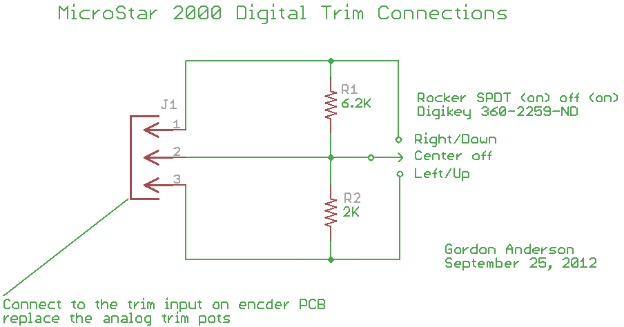
The above circuit configuration for the digital trim switches assume you are using standard analog trim configuration with the battery voltage being applied to the trim pots and the trim pot series resistors set at 4.7K (RN3 on the rev 4.0 Encoder hardware). If you use 5 volt regulated power on your trims and the series resistor values have been set at or below 1K, you can use two 4.7K resistors for R1 and R2 in the circuit shown above.
Connect J1 from the digital trim switch shown above to the channel you would like to convert from analog to digital trim. Pin 3 of the connector is attached to the ground pin of encoder J2 for a given function. For example, pin 3 of the digital aileron trim connector would attach to pin 6 of J2.
The encoder is configurable and you can select which channels you want for digital trims. This means you can have any combination of analog and digital trims you desire.
To configure your system for digital trims, perform the following steps:
- Install firmware version 2.0g or later in your encoder.
- Build the digital trim assemblies and install in your system.
- Start the Encoder in the Test IO mode and make sure the digital trim switches are working properly (press and hold the Option and Preset buttons while powering on the transmitter). Test each installed digital trim by monitoring the ADC channels and making sure the values change similar to the limits you see with analog trims.
- Perform a joystick calibration. This must include calibration of the digital trims. Treat the switches as you would an analog control during the calibration process.
- By default the encoder is configured for analog trims, so you will need to enable the digital trims on the channels you wish to use. To enable digital trims:
- Power up the encoder and enter the CAL mode.
- Select the System Setup option.
- Select the Configuration option.
- In the Configuration menu you will find selections for each of the four channel’s trim controls. Select the trim you are converting to digital and scroll through the options. You will find four digital trim selections labeled 1 through 4. Generally you will select digital trim 1 for aileron, 2 for elevator, 3 for rudder and 4 for throttle. If you would like to setup a cross trim configuration you would select 3 for aileron, 4 for elevator, 1 for rudder, and 2 for throttle.
- Save the changes and exit the CAL mode.
That completes the digital trim setup and the digital trims should now be fully functional. If you would like to activate the center beep function to provide a beep when the trims cross center, you will find details for this option under System Setup when you are in Cal mode.
When the digital trims are adjusted you will see the display change to indicate the trim is being adjusted. The figure below shows an example of the display when the aileron trim is being adjusted digitally. The second line of the display is a bar graph indicating the current trim position.
![]()
The display will show this information while the trim is being adjusted and for 2 seconds after the trim is released. You will also hear the beeps as the trim is being changed. If you hold the trim lever the trim will continuously change at a predefined rate.